
Intro
A few years ago I bought a Midi Fighter 3D from DJ TechTools. After playing with it for a while, I was interested in using it as a game controller, which involves binding buttons to keystrokes. Bome’s Midi Translator is good, but I would like to not use a translation layer. This means I need to use a custom firmware. However, DJ TechTools have open sourced/share sourced almost all Midi Fighter firmware on GitHub[1] except, of course, the MF3D. So I wanted to create at least a working firmware of the MF3D, and to do that, I have to first reverse engineer its hardware design. And after I have finished doing so the MF3D got discontinued, so I guess I would at least do a write-up on the journey, for the sake of those who have one and want to know their hardware.
Background research
Before I opened my MF3D, I looked at the tool for flashing new firmware to it, the MF Utility. I got lucky that the utility has very human readable plugins written in JavaScript, and from there I found the device uses an ATmega32u4 for its microcontroller, a popular one for custom keyboards.

As the MCU is popular, there are a lot of information from the custom keyboard community available for reference, so I don’t have to sift through the whole datasheet.
Between the time of initial research and working on the reverse engineering, I went to design a custom keyboard using the ATmega32u4, following some guides from the community. With that I gained some knowledge on the MCU, and was more confident in dealing with the MF3D.
Disassembly
After doing some research I opened up the MF3D. I did take some pictures for the process, so maybe someday you could find a MF3D disassembly guide on ifixit.
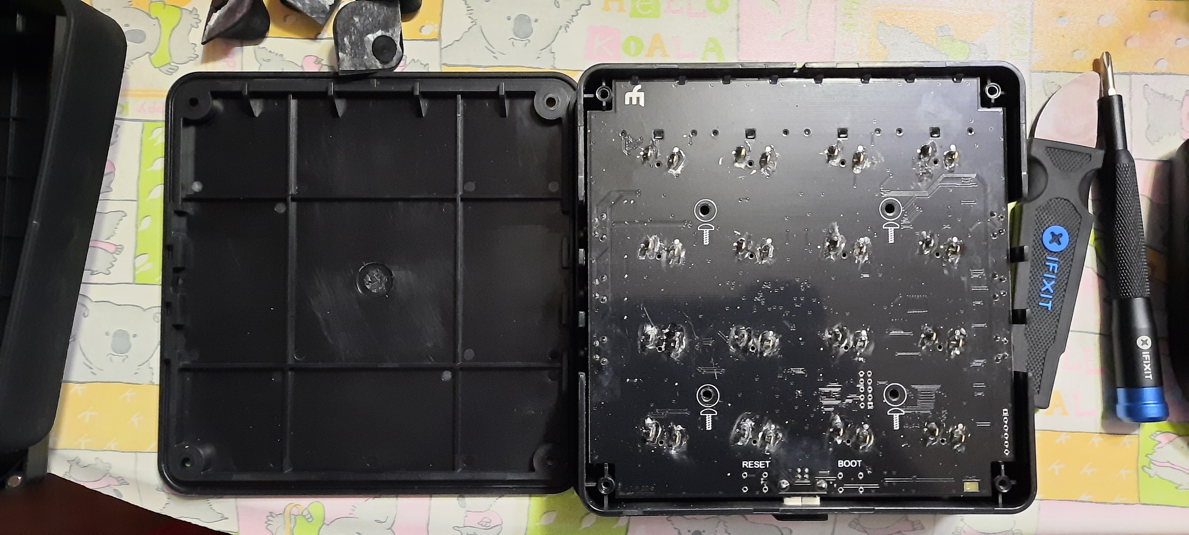
After the four rubber feet, rubber sleeve and four screws were removed, I got to look at the back of the PCB, which there isn’t a whole lot to see. There are only reserved slots for a 1x6 pinout, a 2x5 pinout, and two common through-hole tactile switches.
So I had to dig deeper. The PCB were secured by more than the 4 screws - it was also held on by all the soldered legs of the arcade buttons. I desoldered them all, and unlocked the clips for the four clear plastic things for the bank buttons.
Then I needed to take a clear picture of the PCB. I do have a flatbed scanner, but I don’t know how to change its focus to the traces on PCB, nor how to hold the PCB flat on the side with a massive USB-B port facing down. So I opted for the harder method, taking pictures of sections of the PCB, and piecing them together afterwards with Photoshop. I did this twice for the front and back of the board.
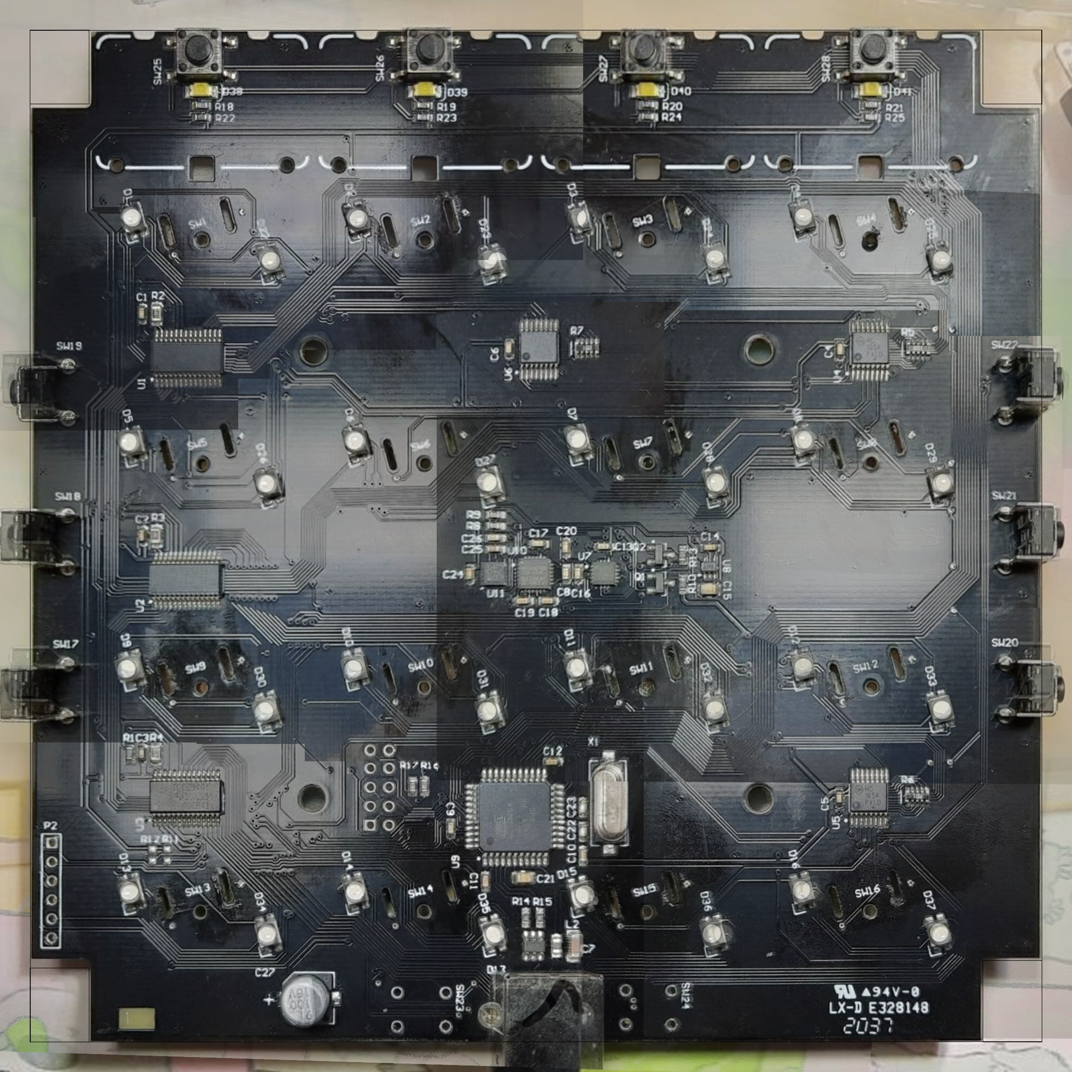
While I have the PCB front side available to me, I also took note of most of the components on the board, which are most of the chips that have markings to identify their model, and resistor values. I also injected 5 volts on the LEDs to check their pinout.
| Chip number on board | Purpose | Model number | Datasheet |
|---|---|---|---|
| U1-3 | LED driver | TLC59461 | datasheet |
| U4-6 | PISO shift register | MC74HC165A | datasheet |
| U7 | Accelerometer | MMA8453Q | datasheet |
| U8 | Regulator | ZXCL330H5TA | datasheet |
| U9 | Microcontroller | ATmega32u4 | datasheet |
| U10 | Gyroscope | ITG-3200 | datasheet |
| U11 | Magnetometer | IST8308 | datasheet |
| D17-21 | ESD protection diode array | USBLC6-2SC6 | datasheet |
However, there is the chip U11 in particular, which I do not know what it does, and googling the markings does not yield any useful result.
Update 20240409: With the help from DRCRecoveryData on GitHub the chip was found. It was an i2c magnetometer.
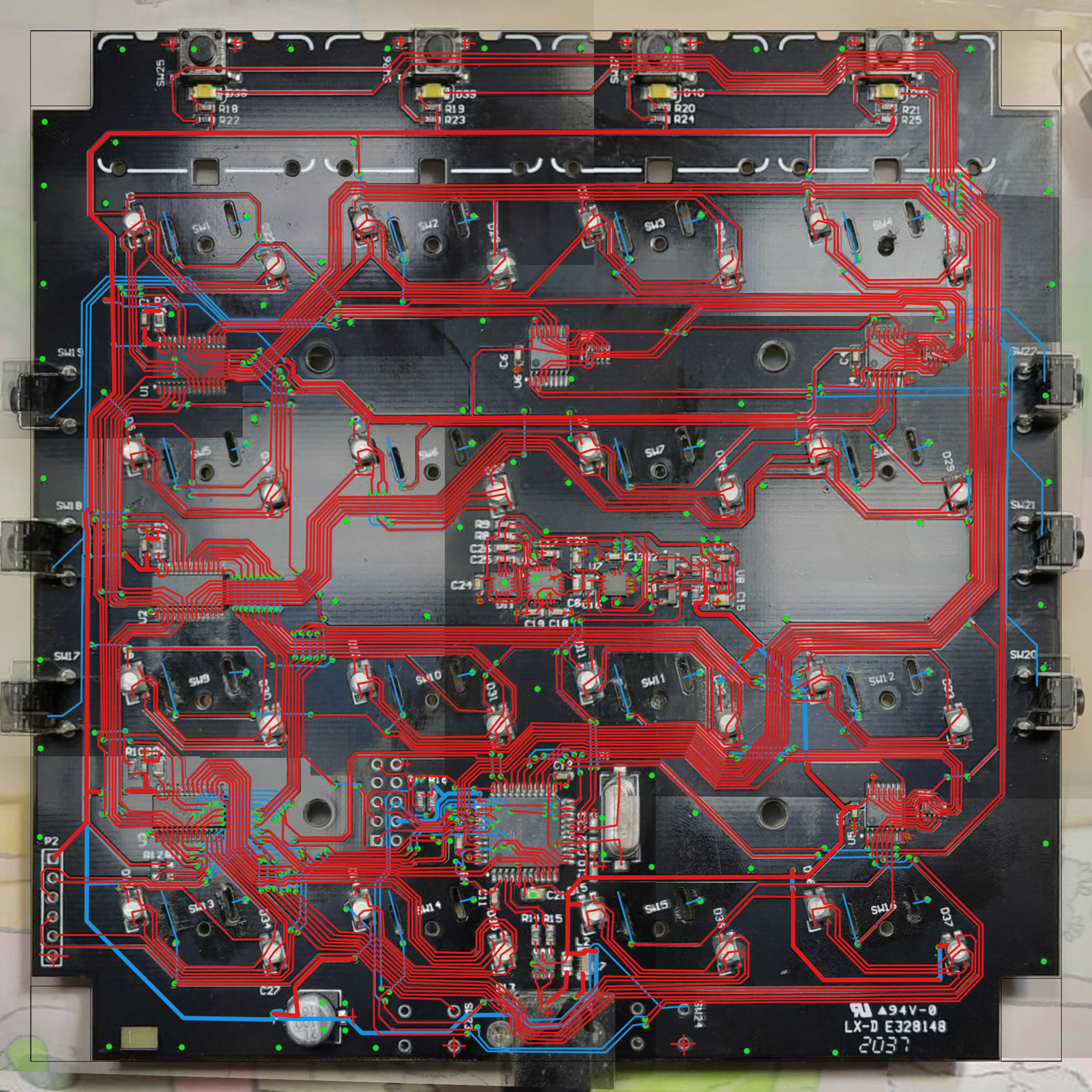
Then I mapped out the traces in Photoshop, with references to the datasheets. It also took me pointing a flashlight at the PCB and inspecting closely several times.
Schematic and PCB
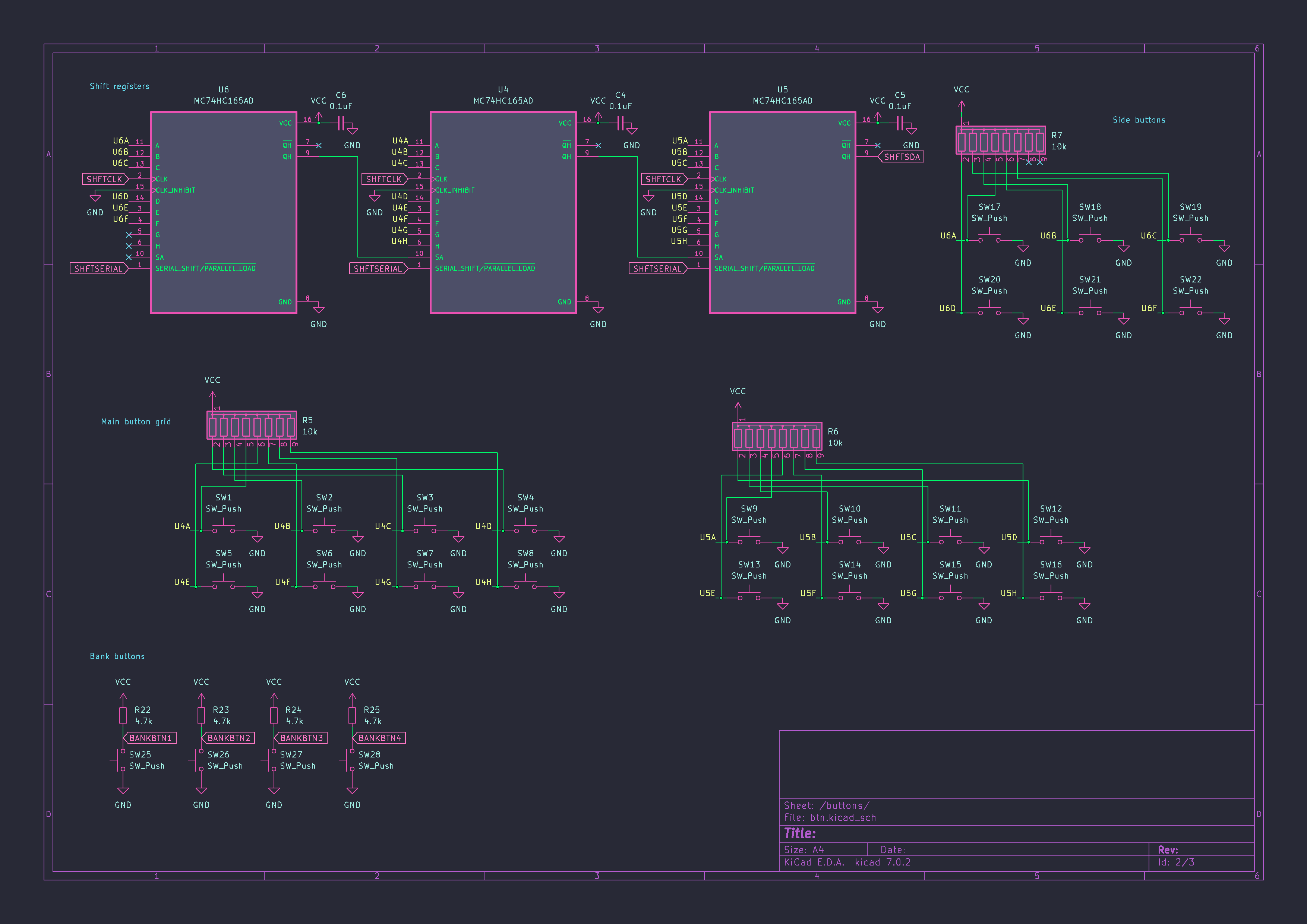
From the traces I marked in the PCB image and the available datasheets, I reconstructed the schematics for the MF3D, other than the U11 related circuitry. I also had to create a few symbols and footprints.
For the guts of the board, there is a gyroscope and an accelerometer on the I2C bus interfacing with the MCU, and the devices run on 3.3V.
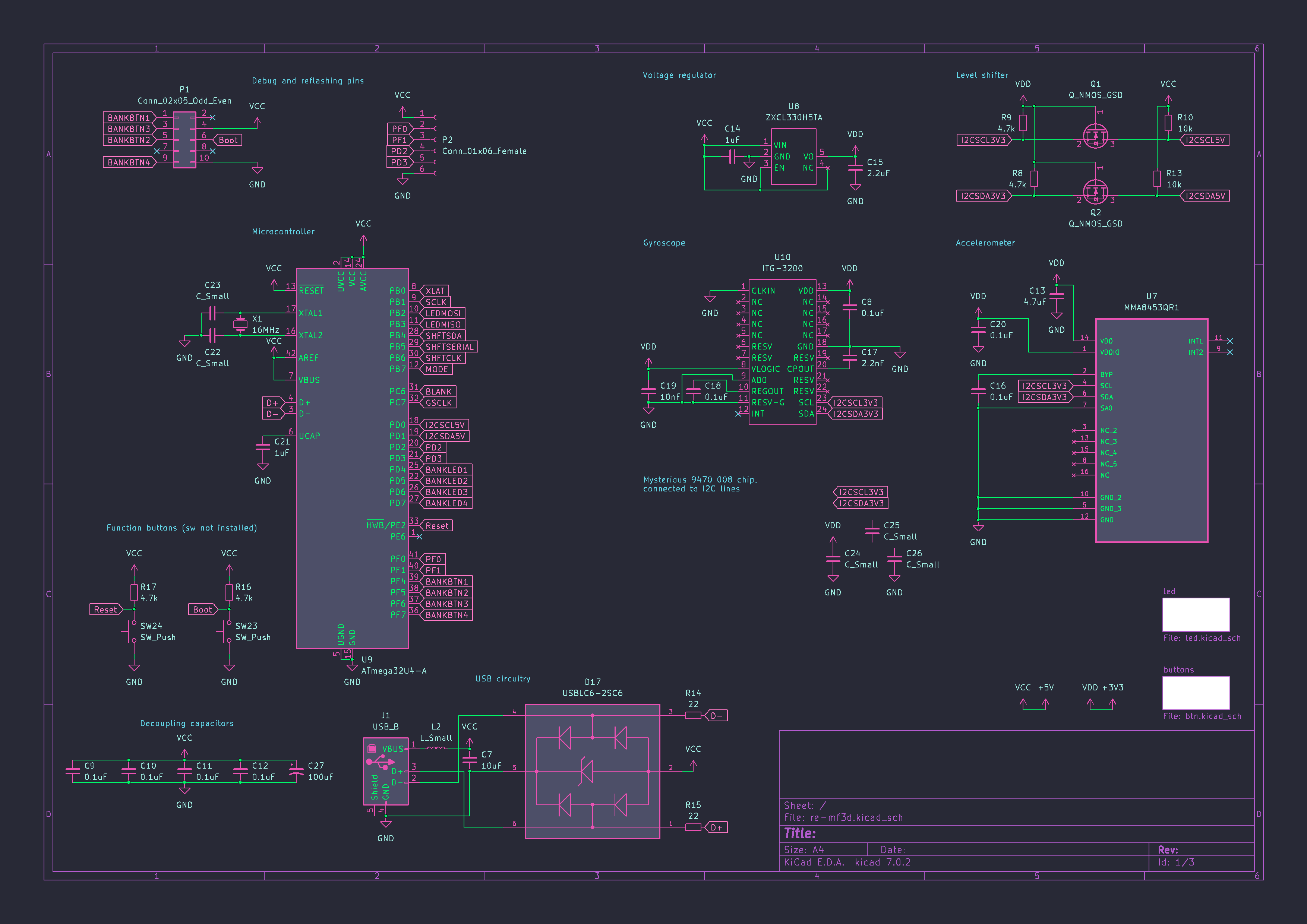
The arcade button LEDs are non-addressable, and are controlled through LED driver chips.
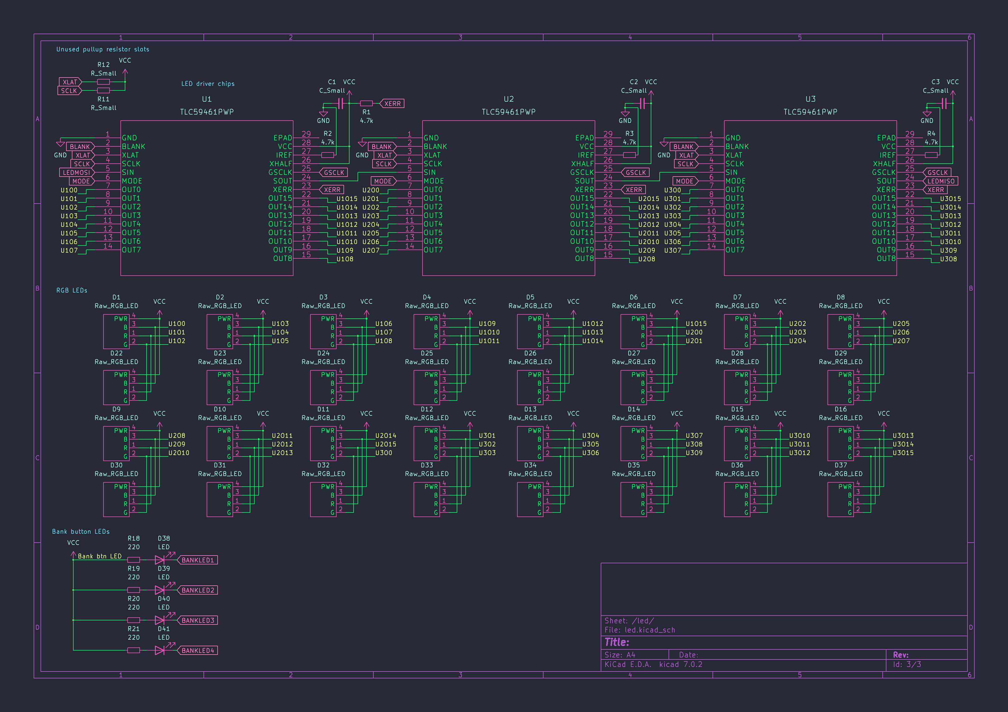
The arcade buttons and side buttons are polled through shift registers, while bank button and their LEDs are polled and controlled on direct pin connection.
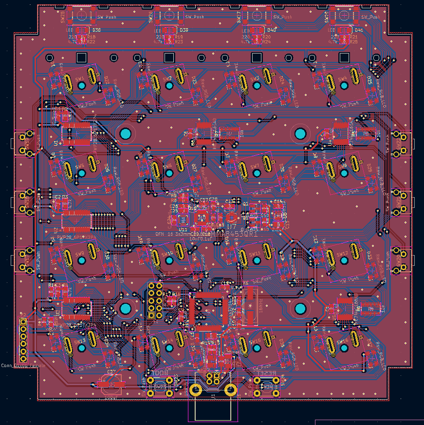
Then I reconstructed the PCB layout, with measuring parts of the PCB using caliper and ruler. This should hopefully be functionally identical to the original board, minus the U11 chip.
Conclusion
After all this was done, I did what I opened up the MF3D to do - replace an arcade button with the spring taking less actuation force than other buttons - then soldered the PCB and closed it back up.
Now with all the information on hand, I should be able to create a custom firmware for it. No promises though.
I have published the results of reverse engineering on GitHub.
Some of the sources are harder to find, like the Midi Fighter 64. ↩︎